


1. Overview
1. Application Occasions
This charger is mainly used for pure electric vehicles to charge power battery packs. It is a high-performance switching power supply that supports constant current charging, constant voltage charging, and constant power charging modes. It features high reliability, high efficiency, and strong shock resistance.
2. Brief Introduction to Product Performance
- Input: 176~264Vac; Output voltage range: 250~420Vdc; Output current range: 0~7A;
- Operating temperature range: -10℃~+50℃;
- Maximum conversion efficiency: >95%;
- High-speed CAN communication bus to realize real-time detection and monitoring functions of the charger;
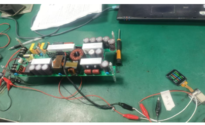
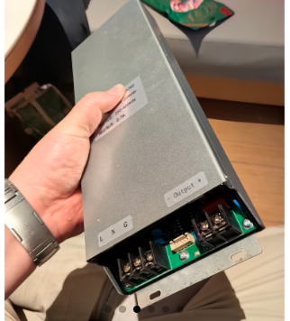
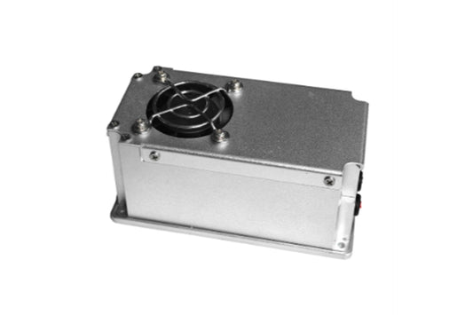
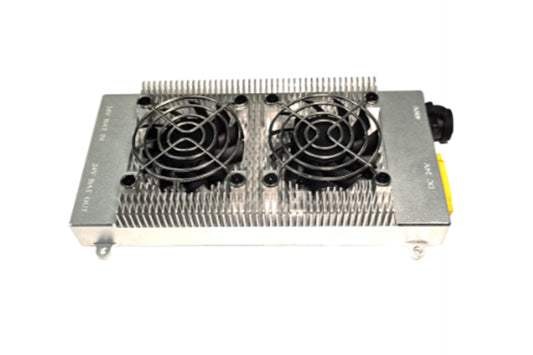
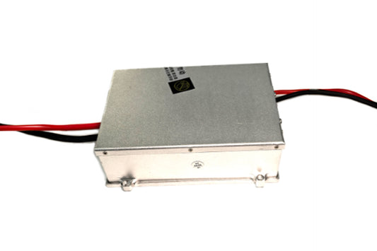
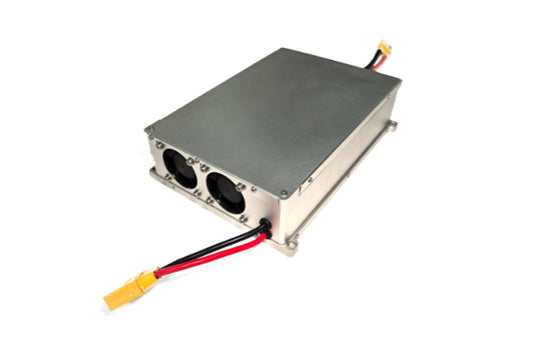
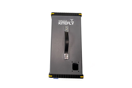
3. Product Picture
2. Environmental Conditions
| Serial No. | Item | Technical Index | Unit | Remarks |
|---|---|---|---|---|
| 1 | Operating Temperature | -10℃~+50℃ | ℃ | |
| 2 | Storage Temperature | -40℃~+95℃ | ℃ | 5-95%RH |
| 3 | Relative Humidity | 5-95 | % | No condensation |
| 4 | Altitude | 0-3000 | m | |
| 5 | Atmospheric Pressure | 70~106 | Kpa | |
| 6 | Noise | < 42dB | ||
| 7 | Sinusoidal Vibration | Sinusoidal vibration: 10~55Hz: displacement 0.35mm; acceleration: 10m/s²; 3 axes, vibration time 30min | ||
| 8 | Shock (Collision) | Acceleration 150m/s²; pulse width 11ms; 10 collisions in each of 6 directions of 3 axes | ||
| 9 | Drop | Drop height 1m; | With packaging, free drop | |
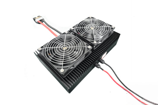
| 10 | Cooling Method | Built-in air cooling |
3. Electrical Characteristics
| 1 | Input Characteristics | |||
|---|---|---|---|---|
| Serial No. | Item | Technical Requirement | Unit | Remarks |
| 1.1 | Rated Input Voltage | 220 | Vac | |
| 1.2 | Input Voltage Range | 100~240 | Vac |
4
| 1.3 | Maximum Input Current | ≤12 | A | 220Vac input, full load. |
|---|---|---|---|---|
| 1.4 | Power Factor | >0.98 | PF | Rated input, above half load |
| 1.5 | Inrush Current at Start-up | ≤15 | A | 220Vac input, full load |
| 1.6 | Input Voltage Detection Accuracy | ±3 | % | Reported via CAN bus |
| 2 | Output Characteristics | |||
| Serial No. | Item | Technical Requirement | Unit | Remarks |
| 2.1 | Rated Output Voltage | 360 | Vdc | |
| 2.2 | Output Voltage Range | 250~420 | Vdc | |
| 2.4 | Rated Output Power | 2500 | W | |
| Input 220Vac, Output | ||||
| 2.5 | Overall Efficiency | >95 | % | 314Vdc, 50%Load, 25℃ |
| 2.6 | Temperature Coefficient | ±0.02 | %/℃ | |
| 2.7 | Output Ripple | ≤4000 | mVp-p | The oscilloscope bandwidth should be 20MHz, with a 10u+104 capacitor connected in parallel with the probe. |
| 2.8 | Start-up Delay | / | The charger shall start only after receiving the BMS command after AC power-on. | |
| 2.9 | Output Rise Time | ≤5000 | ms | |
| 2.10 | Overshoot Amplitude during Start-up/Shutdown | ≤5 | % | |
| 2.11 | Output Response Time | ≤5 | S | Time from when the charger receives the BMS command to when the output reaches the maximum steady-state current |
| 2.12 | Output Current Regulation Accuracy | ±3 | % | Rated input, ≥10% rated load. |
| 2.13 | Static Power Loss Current | ≤3 | mA | Tested under the condition that the charger has no AC input |
| 3 | Protection Characteristics | |||
| Serial No. | Item | Technical Requirement | Unit | Remarks |
| 3.1 | Input Over-voltage Protection | 270~290 | Vac | The whole machine powers off, stores fault information and reports it via CAN bus; Recovery hysteresis ≥5Vac |
| 3.2 | Input Over-voltage Recovery | >265 | Vac | |
| 3.3 | Input Under-voltage Protection | 80~90 | Vac | |
| 3.4 | Input Under-voltage Recovery | <100 | Vac | |
| 3.6 | Output Over-voltage Protection | 440~450 | Vdc | Turn off high-voltage output, store fault information and report it via CAN bus |
| 3.7 | Output Under-voltage Protection | 240~250 | Vdc | Turn off high-voltage output, store fault information and report it via CAN bus |
5
| information and report it via CAN bus | ||||
|---|---|---|---|---|
| 3.8 | Output Over-current Protection | 7.5 | A | If over-current lasts for ≥5S, turn off high-voltage output |
| 3.9 | Output Short-circuit Protection | Yes | Before high-voltage start-up, if output short-circuit is detected, high-voltage output will not start, fault information will be stored and reported via CAN bus, and normal operation will be resumed after the fault is eliminated. During charging, if output short-circuit occurs, turn off the output, store fault information and report it via CAN bus, and lock the machine for protection after 10 short-circuit cycles. | |
| 3.10 | Output Reverse Connection Protection | Yes | Output will not start if reverse-connected, and normal operation can be resumed after the fault is eliminated | |
| 3.11 | Communication Fault Protection | When the charger does not receive the BMS command for 5 consecutive seconds, it will report a CAN communication fault. If a communication fault occurs during the operation of the charger, the charger will turn off the output. It will respond to the operation command only after the CAN bus is restored and stable for 5 seconds. | ||
| 3.12 | Over-temperature Protection | ≥90 | ℃ | If the internal temperature of the power supply lasts for ≥5S, an over-temperature alarm will be reported, and the high-voltage output power will be halved. When the temperature drops to ≤80℃, the charger will resume normal power. |
Note: Output Characteristic Diagram
4.1. CAN_H and CAN_L Characteristics
CAN_H and CAN_L are the CAN buses for communication between the charger and external devices, through which the CAN bus can communicate with the external controller.
CAN Physical Layer Parameters and Interface
| Serial No. | Item | Technical Index | Remarks |
|---|---|---|---|
| 1 | Communication Rate | 250 Kbit/s | Tolerance is ±0.375 kbit/s |
4.2. CAN Bus Communication Protocol
Subject to customer protocol requirements.
6
4. Safety and EMC Characteristics
| Serial No. | Item | Test Condition | Remarks | |
|---|---|---|---|---|
| 1 | Dielectric Strength | Input → Output | 3000Vac/10mA/1min | No arcing, no breakdown |
| Input → Earth (Shell) | 2000Vac/10mA/1min | |||
| Output → Earth (Shell) | 2500Vdc/1mA/1min | |||
| Signal → Earth (Shell) | 500Vdc/1mA/1min | |||
| 2 | Insulation Resistance | Input → Output | ≥20MΩ@ 1000Vdc | Under normal atmospheric pressure, relative humidity of 90%, and test DC voltage of 500V |
| Input → Earth (Shell) | ≥20MΩ@ 1000Vdc | |||
| Output → Earth (Shell) | ≥20MΩ@ 1000Vdc | |||
| Signal → Earth (Shell) | ≥20MΩ@ 1000Vdc | |||
| 3 | Grounding Resistance | ≤0.1 Ω 40A/2min | ||
| 4 | Touch Current | Input Ground to Shell | <3.5mA | 265Vac/60Hz input |
| Input Ground to Output | <0.25mA | Disconnect the output from the earth during the test |
5. Product Label
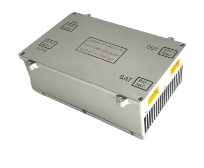
6. Mechanical Dimensions and Connector Definition
1. Overall Dimensions and Connector Definition
Length * Width * Depth = 310mm * 125mm * 41.5mm
7
7. Packaging, Transportation, and Storage
1. Packaging
The packing box shall be marked with product name, model, manufacturer's logo, inspection certificate of the manufacturer's quality department, manufacturing date, etc.; there shall be an accessory list inside the packing box.
2. Transportation
The product shall be packed in a sturdy packing box during transportation. The outer surface of the box shall comply with the provisions of relevant national standards and shall be marked with signs such as "Handle with Care" and "Moisture Proof". The packing boxes containing the products can be transported by any means of transportation. Direct exposure to rain and snow and mechanical impact shall be avoided during transportation.
3. Storage
When not in use, the product shall be stored in the packing box. The warehouse environment shall have a temperature of -10 - 40℃ and a relative humidity not exceeding 80%. There shall be no harmful gases, flammable and explosive products, or corrosive chemicals in the warehouse, and there shall be no strong mechanical vibration, impact, or strong magnetic field. The packing boxes shall be padded to be at least 20cm above the ground and at least 50cm away from walls, heat sources, windows, or air inlets. The storage period under the specified conditions is generally 2 years. After 2 years, the product shall be re-inspected.
8. Reliability Requirements
\(MTBF \geq 100 Khour ;\)Test conditions: 25℃, rated input, full load output, estimated by MIL-HDBK-217F Notice 2 stress method;At 105℃, the service life of electrolytic capacitors is more than 2000 hours.
9. Safety Precautions
- Once the safety protection of the equipment is damaged, the equipment must stop working and be handled in accordance with relevant maintenance regulations.
- When the power supply equipment is moved from a cold environment to a warm environment, condensation may cause electric leakage hazards, so the grounding requirements must be strictly implemented; only qualified personnel are allowed to connect the equipment to the power supply.
- After cutting off the power supply, the equipment must be shut down for five minutes to allow sufficient time for the capacitors to discharge before maintenance can be performed on the power supply equipment.
- Pay attention to safety in use: avoid touching areas marked with safety warnings and high-voltage signs to prevent electric shock and scalding.
10. Referenced Standards and Specifications
QC/T 413-2002 Basic Technical Conditions for Automobile Electrical EquipmentQC/T 895-2011 Conductive On-board Chargers for Electric VehiclesGB/T 2423.1-2001 Environmental Testing for Electrical and Electronic Products, Part 2: Test Methods / Test A: Low TemperatureGB/T 2423.2-2001 Environmental Testing for Electrical and Electronic Products, Part 2: Test Methods / Test B: High TemperatureGB/T 2423.3-1993 Basic Environmental Testing Procedures for Electrical and Electronic Products - Test Ca: Constant Damp Heat Test MethodGB/T 2423.4-1993 Basic Environmental Testing Procedures for Electrical and Electronic Products - Test Db: Alternating Damp Heat Test MethodGB/T 2423.5-1995 Environmental Testing for Electrical and Electronic Products, Part 2: Test Methods / Test Ea and Guide: ShockGB/T 2423.6-1995 Environmental Testing for Electrical and Electronic Products, Part 2: Test Methods / Test Ea and Guide: CollisionGB/T 2423.8-1995 Environmental Testing for Electrical and Electronic Products, Part 2: Test Methods / Test Ed: Free DropGB/T 2423.10-1995 Environmental Testing for Electrical and Electronic Products, Part 2: Test Methods / Test Fc and Guide: Vibration (Sinusoidal)GB/T 2423.11-1997 Environmental Testing for Electrical and Electronic Products, Part 2: Test Methods / Test Fd: Broadband Random Vibration - General RequirementsGB/T 2423.22-2002 Environmental Testing for Electrical and Electronic Products, Part 2: Test N: Temperature ChangeGB/T 14508-93 Mechanical Environmental Conditions for Grade Highway Freight TransportationGB/T 18384.3-2001 Safety Requirements for Electric Vehicles - Part 3: Protection Against Electric Shock for PersonnelGB/T 17619 Electromagnetic Radiation Immunity Limits and Measurement Methods for Automotive Electronic and Electrical ComponentsGB/T 18488.1-2006 Drive Motor Systems for Electric Vehicles - Part 1: Technical ConditionsGB/T 24347-2009 DC/DC Converters for Electric VehiclesGB/T 18655-2010 Limits and Measurement Methods of Radio Disturbance Characteristics for the Protection of On-board Receivers in Measuring, Marine and Internal Combustion Engine EquipmentQ/FT B102-2005 Provisions for Traceability Identification of Vehicle Product Components
9
GB/T 17626.2-2006 Electromagnetic Compatibility - Testing and Measurement Techniques - Electrostatic Discharge Immunity TestGB/T 17626.3-2006 Electromagnetic Compatibility - Testing and Measurement Techniques - Radiated Radio Frequency Electromagnetic Field Immunity TestGB/T 17626.4-2008 Electromagnetic Compatibility - Testing and Measurement Techniques - Electrical Fast Transient/Burst Immunity TestGB/T 17626.5-2008 Electromagnetic Compatibility - Testing and Measurement Techniques - Surge (Shock) Immunity TestGB4943-2001 Safety of Information Technology EquipmentGB14287.1-2005 Electrical Fire Monitoring Systems - Part 1: Electrical Fire Monitoring Devices