


1. Overview
1.1 Application Occasions
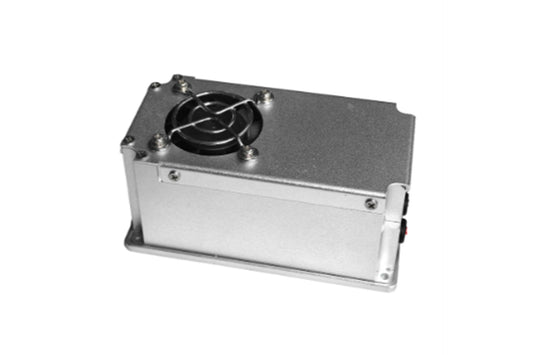
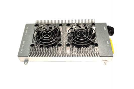
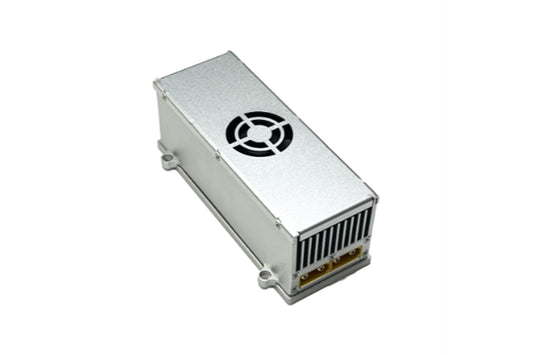
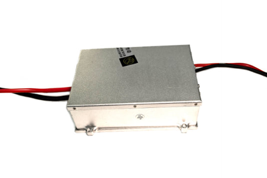
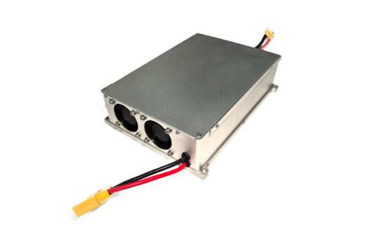
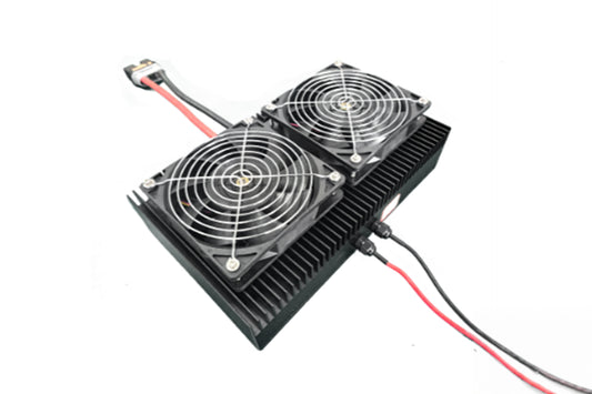
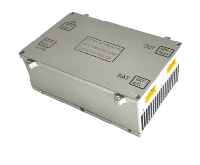
This high-voltage DC power supply is a custom-made special power supply, featuring small size, light weight, high efficiency, and built-in fan for heat dissipation. Its maximum operating efficiency is ≥97%. The power module adopts an aluminum shell design, which is lightweight, aesthetically pleasing, and waterproof. It can be used as a substitute for imported high-voltage DC module power supplies.
1.2 Product Features
- DC-DC Isolated Power Converter: Converts the input 800V DC power into 50V DC power in an isolated manner, with a total output power of 4000W.
- High power density, small size, and light weight.
- Designed to meet power supply reliability requirements: Equipped with over/under voltage protection for input, and overvoltage protection, current limiting, short-circuit protection, and overtemperature protection for output.
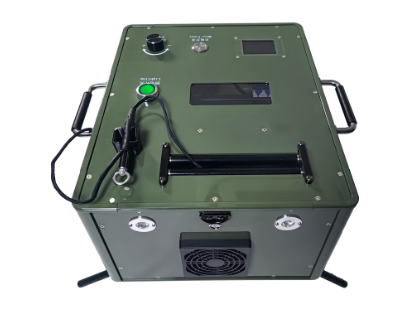
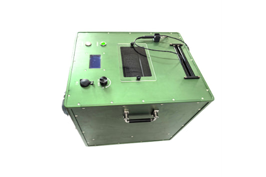
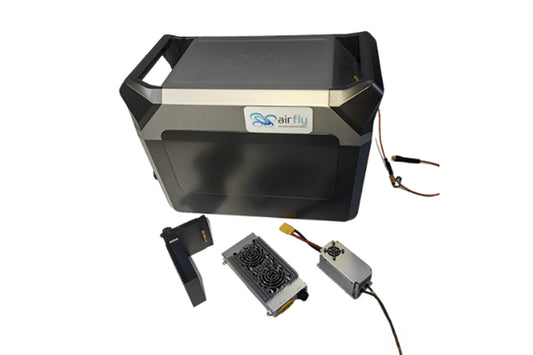
1.3 Product Photos
(Photos to be inserted here)
1.4 Main Product Specifications
| Input Voltage Range | Rated Output Voltage | Maximum Output Power | Efficiency | Voltage Regulation Accuracy | Output Ripple and Noise |
|---|---|---|---|---|---|
| 680~800Vdc | 50±0.5Vdc | 4000W | ≥97% | ≤±1% | ≤±2%Vo |
4
2. Environmental Conditions
| Serial No. | Item | Technical Index | Unit | Remarks |
|---|---|---|---|---|
| 1 | Operating Temperature | -40℃~+50℃ | ℃ | |
| 2 | Storage Temperature | -40℃~+80℃ | ℃ | / |
| 3 | Relative Humidity | ≤95 | % | No condensation (40℃±2℃) |
| 4 | Altitude | 0-2000 | m | |
| 5 | Atmospheric Pressure | 76~106 | Kpa | / |
| 6 | Heat Dissipation Method | Built-in Air Cooling | / | / |
3. Electrical Characteristics
3.1 Input Characteristics
| Serial No. | Item | Technical Requirement | Unit | Remarks |
|---|---|---|---|---|
| 1.1 | Rated Input Voltage | 750 | Vdc | |
| 1.2 | Input Voltage Range | 680~800 | Vdc | |
| 1.3 | Maximum Input Current | 7 | A | In=680Vdc, Po=4000W |
3.2 Output Characteristics
| Serial No. | Item | Technical Requirement | Unit | Remarks |
|---|---|---|---|---|
| 2.1 | Rated Output Voltage | 50 | Vdc | / |
| 2.2 | Output Voltage Range | 47~50.5 | Vdc | |
| 2.3 | Rated Output Current | 80 | A | / |
| 2.4 | Maximum Output Current | 88 | A | / |
| 2.5 | Maximum Output Power | 4000 | W | / |
| 2.6 | Output Efficiency | ≥97 | % | In=750Vdc, Half Load |
| 2.7 | Voltage Regulation Accuracy | ±1 | % | / |
| 2.8 | Source Regulation | ±1 | % | / |
| 2.9 | Load Regulation | ±1 | % | / |
| 2.10 | Output Ripple and Noise | ±2 | %/Vo | Bandwidth limited to 20MHz; 10uF electrolytic capacitor and 0.1uF film capacitor connected in parallel at the test terminal; Rated load |
| 2.11 | Temperature Coefficient | ±0.02 | %/℃ | / |
| 2.12 | Output Rise Time | ≤200 | ms | / |
| 2.13 | Power-on Output Delay | ≤5 | S | Rated input |
| 2.14 | Power-on/Power-off Overshoot Amplitude | △V: ≤±5 | % | / |
| 2.15 | Dynamic Response Overshoot | △V: ≤±5 | % | 25%~50%~25% or 50%~75%~50% load change, 25℃ |
| 2.16 | Dynamic Response Recovery Time | ≤2 | ms | 25%~50%~25% or 50%~75%~50% load change, 25℃ |
3.3 Protection Characteristics
| Serial No. | Item | Technical Requirement | Unit | Remarks |
|---|---|---|---|---|
| 3.1 | Input Undervoltage Protection | 620~640 | Vdc | |
| 3.2 | Input Undervoltage Recovery | ≤650 | Vdc | Hysteresis >10V |
| 3.3 | Input Overvoltage Protection | 810~830 | Vdc | |
| 3.4 | Input Overvoltage Recovery | ≥800 | Vdc | Hysteresis >10V |
| 3.5 | Input Reverse Connection Protection | No damage in case of reverse connection | - | Input 800Vdc reversed |
| 3.6 | Output Overvoltage Protection | 55~59 | Vdc | Self-recoverable |
| 3.7 | Output Overcurrent Protection | 86~95 | A | Self-recoverable |
| 3.8 | Output Short-Circuit Protection | Available | - | Self-recoverable |
| 3.9 | Overtemperature Protection | Available | ℃ | Self-recoverable |
3.4 Parallel Current Sharing
| Serial No. | Item | Technical Requirement | Unit | Remarks |
|---|---|---|---|---|
| 4.1 | Current Sharing Imbalance Degree | ≤5 | % | Output >50% LOAD |
| 4.2 | Parallel Connection Method | Current sharing bus signals connected in parallel; load outputs connected in parallel | - | |
| 4.3 | Maximum Parallel Quantity | ≤8 | PCS |
5
4. Safety Characteristics
| Serial No. | Item | Test Condition | Remarks |
|---|---|---|---|
| 1 | Dielectric Strength | Input to Output: 2500Vdc/2mA/1min
|
No arcing, no breakdown |
| 2 | Insulation Resistance | Input to Output: ≥10MΩ @ 500Vdc
|
Under normal atmospheric pressure, relative humidity 90%, test DC voltage 500V |
5. Other Characteristics
5.1 Flame Retardant Requirement
- The flame retardant grade of the PCB used in the system shall meet the V-0 requirement specified in GB4943.1-2011.
- The flame retardant grade of the insulated cables shall meet the requirements specified in GB/T 18380.12-2008.
- The flame retardant grade of other insulating materials shall meet the V1 requirement specified in GB4943.1-2011.
5.2 System Noise
The system noise shall not exceed 55dB(A).
5.3 System Reliability
- MTBF (Mean Time Between Failures) ≥ 100Khour;
- Test Conditions: 25℃, rated input, full-load output, estimated by MIL-HDBK-217F Notice2 stress method.
5.4 Protection Grade
The protection grade shall meet the IP54 requirement. No water accumulation is allowed on the top of the power supply enclosure.
5.5 Three-proof (Moisture-proof, Mildew-proof, Salt Spray-proof)
The printed circuit boards, connectors, and other circuits in the product shall be treated with moisture-proof, mildew-proof, and salt spray-proof measures. Among them, the salt spray resistance shall meet the requirements in Table 9 of GB/T 4797.6, enabling the product to operate normally in outdoor humid and salt spray environments.
6. Product Label

7. Mechanical Dimensions and Connector Definition

8. Packaging, Transportation, Storage
8.1 Packaging
- The packing box shall be marked with product name, model, manufacturer's logo, inspection certificate from the manufacturer's quality department, manufacturing date, etc.
- An accessory list shall be included in the packing box.
8.2 Transportation
- The product shall be packed in a sturdy packing box during transportation.
- The exterior of the box shall comply with the provisions of relevant national standards and be marked with signs such as "Handle with Care" and "Moisture-proof".
- The packing boxes containing the products can be transported by any means of transportation.
- During transportation, direct exposure to rain and snow and mechanical impact shall be avoided.
8.3 Storage
- Unused products shall be stored in the packing boxes.
- The warehouse environment shall have a temperature of -10℃~40℃ and a relative humidity not exceeding 80%.
- The warehouse shall be free of harmful gases, flammable and explosive products, and corrosive chemicals. There shall be no strong mechanical vibration, impact, or strong magnetic field.
- The packing boxes shall be placed at least 20cm above the ground and at least 50cm away from walls, heat sources, windows, or air inlets.
- The storage period under the specified conditions is generally 2 years. After 2 years, the product shall be re-inspected before use.
9. Safety Precautions
- Once the safety protection of the equipment is damaged, the equipment must be stopped and handled in accordance with the relevant maintenance regulations.
- When the power supply equipment is moved from a cold environment to a warm environment, condensation may cause electric leakage hazards. Therefore, the grounding requirement must be strictly implemented; only qualified personnel are allowed to connect the equipment to the power supply.
- Before conducting maintenance on the power supply equipment, the power supply must be cut off and the equipment must be shut down for 5 minutes to allow sufficient time for the capacitors to discharge.
- Pay attention to safety in use: Avoid touching parts marked with safety warning signs or high-voltage signs to prevent electric shock or burns.
8
10. Referenced Standards and Specifications
- GB/T 2423.1-2001 Environmental Testing for Electrical and Electronic Products - Part 2: Test Methods - Test A: Low Temperature
- GB/T 2423.2-2001 Environmental Testing for Electrical and Electronic Products - Part 2: Test Methods - Test B: High Temperature
- GB/T 2423.3-1993 Basic Environmental Testing Procedures for Electrical and Electronic Products - Test Ca: Steady Damp Heat Test Method
- GB/T 2423.4-1993 Basic Environmental Testing Procedures for Electrical and Electronic Products - Test Db: Alternating Damp Heat Test Method
- GB/T 2423.5-1995 Environmental Testing for Electrical and Electronic Products - Part 2: Test Methods - Test Ea and Guidance: Shock
- GB/T 2423.6-1995 Environmental Testing for Electrical and Electronic Products - Part 2: Test Methods - Test Ea and Guidance: Bump
- GB/T 2423.8-1995 Environmental Testing for Electrical and Electronic Products - Part 2: Test Methods - Test Ed: Free Fall
- GB/T 2423.10-1995 Environmental Testing for Electrical and Electronic Products - Part 2: Test Methods - Test Fc and Guidance: Vibration (Sinusoidal)
- GB/T 2423.11-1997 Environmental Testing for Electrical and Electronic Products - Part 2: Test Methods - Test Fd: Broadband Random Vibration - General Requirements
- GB/T 2423.22-2002 Environmental Testing for Electrical and Electronic Products - Part 2: Test Methods - Test N: Temperature Change
- GB/T 14508-93 Mechanical Environmental Conditions for Grade Highway Freight Transportation
- EN55022:1998 Information Technology Equipment - Radio Disturbance Characteristics - Limits and Measurement Methods
- EN55024:1998 Information Technology Equipment - Immunity Characteristics - Limits and Measurement Methods
- CEI IEC 61000-4-2 2001 Electromagnetic Compatibility (EMC) - Testing and Measurement Techniques - Electrostatic Discharge Immunity Test
- CEI IEC 61000-4-3 2002 Electromagnetic Compatibility (EMC) - Testing and Measurement Techniques - Radiated, Radio-Frequency, Electromagnetic Field Immunity Test
- CEI IEC 61000-4-4 1998 Electromagnetic Compatibility (EMC) - Testing and Measurement Techniques - Electrical Fast Transient/Burst Immunity Test
- CEI IEC 61000-4-5 1999 Electromagnetic Compatibility (EMC) - Testing and Measurement Techniques - Surge (Impact) Immunity Test
- CEI IEC 61000-4-6 2001 Electromagnetic Compatibility (EMC) - Testing and Measurement Techniques - Immunity to Conducted Disturbances, Induced by Radio-Frequency Fields
- CEI IEC 61000-4-8 1993 Electromagnetic Compatibility (EMC) - Testing and Measurement Techniques - Power Frequency Magnetic Field Immunity Test
- CEI IEC 61000-4-11 1994 Electromagnetic Compatibility (EMC) - Testing and Measurement Techniques - Voltage Dips, Short Interruptions and Voltage Variations Immunity Tests
- CEI IEC 61000-4-29 2000 Electromagnetic Compatibility (EMC) - Testing and Measurement Techniques - Voltage Dips, Short Interruptions and Voltage Variations Immunity Tests for DC Input Ports
- IEC 61000-3-2 2001 Electromagnetic Compatibility (EMC) - Limits - Limits for Harmonic Current Emissions (Equipment Input Current ≤16A per Phase)
- IEC 61000-3-3 1994 Electromagnetic Compatibility (EMC) - Limits - Limitation of Voltage Fluctuations and Flicker in Low-Voltage Supply Systems (Equipment Rated Current ≤16A)
- GB4943-2001 Safety of Information Technology Equipment
- YD/T 282-2000 General Reliability Test Methods for Communication Equipment
- GB/T 13722-92 Technical Requirements and Test Methods for Mobile Communication Power Supplies
- YD/T 732-95 Inspection Methods for DC-DC Converters for Telecommunication
- YD/T 731-2002 High-Frequency Switching Rectifiers for Telecommunication
- GB14287.1-2005 Electrical Fire Monitoring Systems - Part 1: Electrical Fire Monitoring Devices