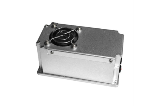
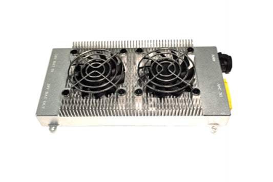
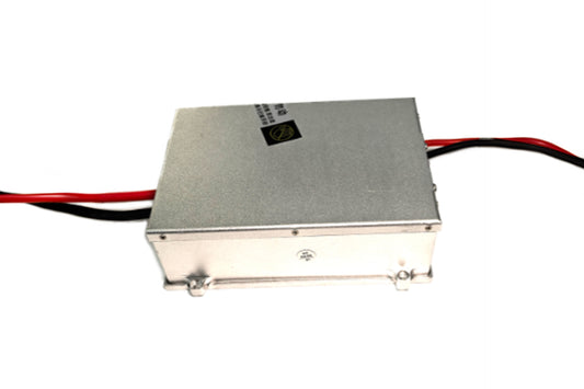
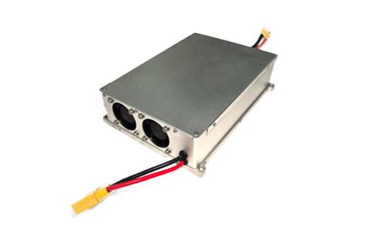
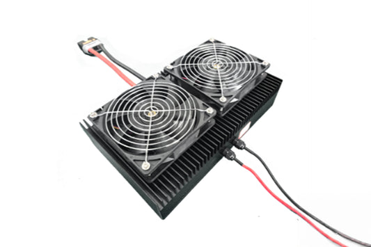
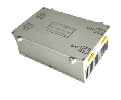
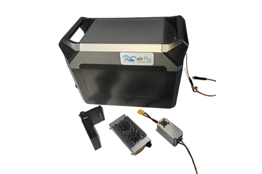
This high-voltage DC power supply is a custom-made special power supply, featuring small size, light weight, high efficiency, and built-in fan for heat dissipation. Its maximum operating efficiency is ≥97%. The power module adopts an aluminum shell design, which is lightweight, aesthetically pleasing, and waterproof, and can be used as a substitute for imported high-voltage DC module power supplies.
- DC-DC isolated power converter: Converts the input 1000V DC power into 50V DC power in an isolated manner, with a rated output power of 18KW.
- High power density, small size, and light weight.
- Designed to meet power supply reliability requirements: Equipped with over/under-voltage protection for input, and over-voltage protection, current limiting, short-circuit protection, and over-temperature protection for output.
- The flame retardant grade of the PCB used in the system shall meet the V-0 requirement specified in GB4943.1-2011.
- The flame retardant grade of the insulated cables shall meet the requirement specified in GB/T 18380.12-2008.
- The flame retardant grade of other insulating materials shall meet the V1 requirement specified in GB4943.1-2011.
The system noise shall not exceed 45dB(A).
- Test conditions: 25℃, rated input, full-load output; predicted by the stress method in MIL-HDBK-217F Notice 2.
- (Note: The original document lacks specific MTBF data; it is recommended to supplement it according to actual product performance if needed)
The protection level shall meet the IP65 requirement. No water accumulation is allowed on the top of the power supply enclosure.
The printed circuit boards, connectors, and other circuits in the product shall be treated with moisture-proof, mildew-proof, and salt spray-proof measures. Among them, the salt spray resistance shall meet the requirements in Table 9 of GB/T 4797.6, ensuring that the product can operate normally in outdoor humid and sweat-salt spray environments.

Net Weight: 8.2Kg
- The packing box shall be marked with the product name, model, manufacturer's logo, inspection certificate of the manufacturer's quality department, manufacturing date, etc.
- An accessory list shall be included in the packing box.
- The product shall be packed in a sturdy packing box during transportation.
- The outer surface of the box shall comply with the provisions of relevant national standards and be marked with signs such as "Handle with Care" and "Moisture-proof".
- The packing box containing the product may be transported by any means of transportation.
- During transportation, direct exposure to rain and snow and mechanical impact shall be avoided.
- Unused products shall be stored in the packing box.
- The warehouse environment shall have a temperature of -10~40℃ and a relative humidity not exceeding 80%.
- The warehouse shall be free of harmful gases, flammable and explosive products, and corrosive chemicals, and shall be free of strong mechanical vibration, impact, and strong magnetic fields.
- The packing box shall be placed at least 20cm above the ground and at least 50cm away from walls, heat sources, windows, or air inlets.
- The storage period under the specified conditions is generally 2 years. After 2 years, the product shall be re-inspected before use.
- Once the safety protection of the equipment is damaged, the equipment must be stopped and handled in accordance with the relevant maintenance regulations.
- When the power supply equipment is moved from a cold environment to a warm environment, condensation may cause electric leakage hazards. Therefore, the grounding requirement must be strictly implemented; only qualified personnel are allowed to connect the equipment to the power supply.
- After the power supply is cut off, the equipment must be shut down for 5 minutes to allow sufficient time for the capacitors to discharge before maintenance work is performed on the power supply equipment.
- Pay attention to safety in use: Avoid touching parts marked with safety warning signs or high-voltage signs to prevent electric shock or burns.
- GB/T 2423.1-2001 Environmental Testing for Electric and Electronic Products - Part 2: Test Methods - Test A: Low Temperature
- GB/T 2423.2-2001 Environmental Testing for Electric and Electronic Products - Part 2: Test Methods - Test B: High Temperature
- GB/T 2423.3-1993 Basic Environmental Testing Procedures for Electric and Electronic Products - Test Ca: Steady-state Damp Heat Test Method
- GB/T 2423.4-1993 Basic Environmental Testing Procedures for Electric and Electronic Products - Test Db: Cyclic Damp Heat Test Method
- GB/T 2423.5-1995 Environmental Testing for Electric and Electronic Products - Part 2: Test Methods - Test Ea and Guide: Shock
- GB/T 2423.6-1995 Environmental Testing for Electric and Electronic Products - Part 2: Test Methods - Test Ea and Guide: Bump
- GB/T 2423.8-1995 Environmental Testing for Electric and Electronic Products - Part 2: Test Methods - Test Ed: Free Fall
- GB/T 2423.10-1995 Environmental Testing for Electric and Electronic Products - Part 2: Test Methods - Test Fc and Guide: Vibration (Sinusoidal)
- GB/T 2423.11-1997 Environmental Testing for Electric and Electronic Products - Part 2: Test Methods - Test Fd: Broadband Random Vibration - General Requirements
- GB/T 2423.22-2002 Environmental Testing for Electric and Electronic Products - Part 2: Test Methods - Test N: Temperature Change
- GB/T 14508-93 Mechanical Environmental Conditions for Road Freight Transportation
- EN55022:1998 Information Technology Equipment - Radio Disturbance Characteristics - Limits and Measurement Methods
- EN55024:1998 Information Technology Equipment - Immunity Characteristics - Limits and Measurement Methods
- CEI IEC 61000-4-2 2001 Electromagnetic Compatibility (EMC) - Testing and Measurement Techniques - Electrostatic Discharge Immunity Test
- CEI IEC 61000-4-3 2002 Electromagnetic Compatibility (EMC) - Testing and Measurement Techniques - Radiated, Radio-frequency, Electromagnetic Field Immunity Test
- CEI IEC 61000-4-4 1998 Electromagnetic Compatibility (EMC) - Testing and Measurement Techniques - Electrical Fast Transient/Burst Immunity Test
- CEI IEC 61000-4-5 1999 Electromagnetic Compatibility (EMC) - Testing and Measurement Techniques - Surge (Impact) Immunity Test
- CEI IEC 61000-4-6 2001 Electromagnetic Compatibility (EMC) - Testing and Measurement Techniques - Immunity to Conducted Disturbances, Induced by Radio-frequency Fields
- CEI IEC 61000-4-8 1993 Electromagnetic Compatibility (EMC) - Testing and Measurement Techniques - Power Frequency Magnetic Field Immunity Test
- CEI IEC 61000-4-11 1994 Electromagnetic Compatibility (EMC) - Testing and Measurement Techniques - Voltage Dips, Short Interruptions and Voltage Variations Immunity Tests
- CEI IEC 61000-4-29 2000 Electromagnetic Compatibility (EMC) - Testing and Measurement Techniques - Voltage Dips, Short Interruptions and Voltage Variations Immunity Tests for DC Input Ports
- IEC 61000-3-2 2001 Electromagnetic Compatibility (EMC) - Limits - Limits for Harmonic Current Emissions (Equipment Input Current ≤16A per Phase)
- IEC 61000-3-3 1994 Electromagnetic Compatibility (EMC) - Limits - Limitation of Voltage Fluctuations and Flicker in Low-voltage Supply Systems (Equipment Rated Current ≤16A)
- GB4943-2001 Safety of Information Technology Equipment
- YD/T 282-2000 General Test Method for Reliability of Telecommunication Equipment
- GB/T 13722-92 Technical Requirements and Test Methods for Mobile Communication Power Supplies
- YD/T 732-95 Test Method for DC-DC Converters for Telecommunication
- YD/T 731-2002 High-frequency Switching Rectifiers for Telecommunication
- GB14287.1-2005 Electrical Fire Monitoring Systems - Part 1: Electrical Fire Monitoring Devices


