


1. Overview
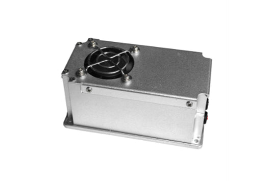
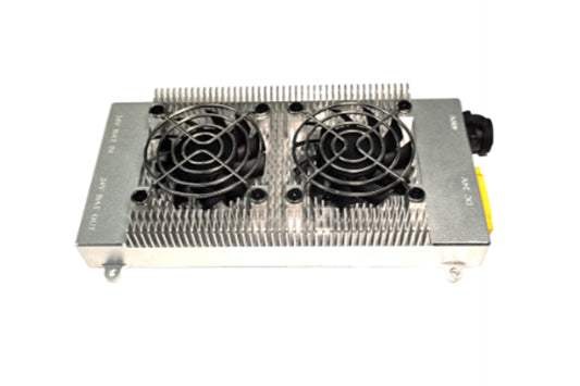
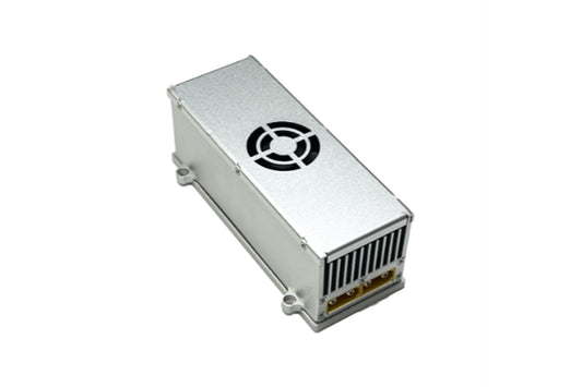
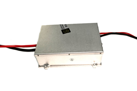
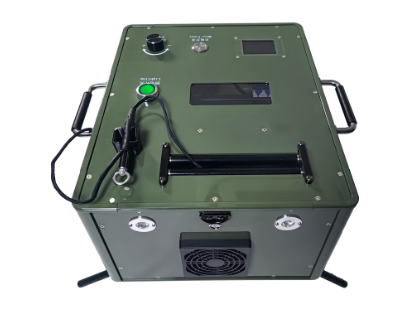
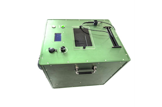
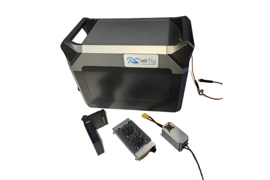
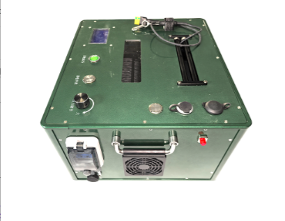
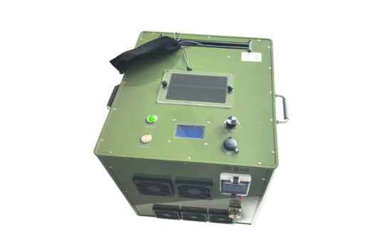
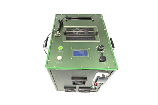
This power supply adopts the latest soft-switching technology and operates in an open-loop mode, with an input-output ratio of 8:1. It is equipped with input over-voltage and under-voltage protection, as well as output over-voltage and over-current protection. Additionally, it features a compact size, light weight, and waterproof function (IP65), making it widely applicable to devices such as unmanned aerial vehicles (UAVs). Its characteristics are as follows:
- Long service life, fast dynamic response, and high efficiency;
- Seamless switching with batteries, no voltage transient drop;
- High-reliability modular design;
- Widely used as a power supply for tethered lighting UAVs.
1.1 Purpose
This power supply specification is for a customized power supply developed for design and development purposes. Its functions are:
- Serving as the basis for design and development by the R&D department;
- Serving as the basis for production and inspection by the production department;
- Serving as the basis for inspection and qualification judgment by the quality department;
- Serving as the basis for customers to select power supplies.
1.2 Scope of Application
This document specifies the specifications of the AF-400S50-4K power supply designed by our company. It can be used as the basis for production operations by the production and quality departments, and also as a reference for customers in selecting power supplies.
2. Functional Description
This document is the specification for the AF-400S50-4K power supply. It has a rated input range of 360-430Vdc, an output of 45-53.5Vdc/80A, a rated power of 3500W, and a peak power of 4300W. The power supply is equipped with output over-current protection, output short-circuit protection, output over-voltage protection, and over-temperature protection functions.
3. Operating Environment
| Parameter | Minimum Value | Typical Value | Maximum Value | Unit | Remarks/Conditions |
|---|---|---|---|---|---|
| Operating Temperature | -40 | - | +55 | ℃ | Forced Air Cooling |
| Storage Temperature | -55 | 25 | +105 | ℃ | |
| Relative Humidity | 5 | - | 95 | % | No Condensation |
| Storage Humidity | 5 | - | 95 | % | No Condensation |
| Atmospheric Pressure | 54 | - | 106 | kPa | |
| Altitude | - | - | 5000 | m | |
| Protection Class | IP65 |
4. Electrical Characteristics
4.1 Basic Input Characteristics
| Item | Minimum Value | Typical Value | Maximum Value | Unit | Remarks/Conditions |
|---|---|---|---|---|---|
| Rated Input Voltage Range | 360 | 400 | 430 | Vdc | Full Load Mode |
| Maximum Limit Input Voltage | 410 | 415 | 450 | Vdc | The power supply will not be damaged under this condition |
| Maximum Input Current | - | - | 11 | A | Vin=360Vdc, Output Rated Load |
| Input Inrush Current | - | - | 50 | A | Vin=410Vdc, Output Full Load |
| Start-up with Load | 360 | 400 | 430 | V | Rated Power Below 5A |
4.2 Output Characteristics
4.2.1 Basic Output Characteristics
| Item | Minimum Value | Typical Value | Maximum Value | Unit | Remarks/Conditions |
|---|---|---|---|---|---|
| Output Voltage 1 Range | 45 | 50 | 53.5 | Vdc | |
| OUT Load Regulation | - | - | ±3 | % | |
| OUT Load Regulation | - | - | ±5 | % | |
| Efficiency | 97 | 98 | 98.3 | % | Input 380-420Vdc, Output Full Load |
| Ripple and Noise | 350 | - | 430 | mVp-p | 20MHz Bandwidth Limitation |
| OUT Current | - | 70 | 80 | A | |
| Output Voltage Overshoot Amplitude | - | ±5 | - | % | |
| Transient Overshoot Amplitude | - | ±5 | - | % | Ta=25℃, 50%-75%-50%, di/dt=0.1A/µs Load Step Change |
| Transient Recovery Time | - | 200 | - | µs | Ta=25℃, 50%-75%-50%, di/dt=0.1A/µs Load Step Change |
| Temperature Coefficient | - | ±0.02 | - | %/℃ |
4.2.2 Protection Characteristics
| Item | Minimum Value | Typical Value | Maximum Value | Unit | Remarks/Conditions |
|---|---|---|---|---|---|
| Input Over-Voltage Protection | 455 | 460 | 465 | V | |
| Input Under-Voltage Protection | 310 | 315 | 320 | V | |
| Output Over-Current Protection | - | 105 | - | A | Locked, returns to normal after restart |
| Output Short-Circuit Protection | Available | - | - | - | Locked, returns to normal after restart |
| Over-Temperature Protection Function | Available | - | - | - | Self-recoverable |
| Power Supply Parallel Operation | - | Passive Current Sharing for Parallel Operation | - | - |
4.3 Other Specifications
| Item | Requirement | Remarks |
|---|---|---|
| Three-Prevention Design | PCB Coated with Three-Prevention Paint | |
| Heat Dissipation | Forced Air Cooling | |
| MTBF | ≥100K | H |
| Overall Weight | ≤0.8 | kg |
| Power Supply Indicator | 2 Green LEDs Stay On During Operation, Turn Off Otherwise | Built-in |
5. Safety Specifications
| Item | Grade | Standard (or Test Condition) | ||
|---|---|---|---|---|
| Insulation Withstand Voltage | Input to Output | 3000 | Vdc | No Breakdown, No Arcing. Test Condition: 5mA/min, Rise Rate 500V/s |
| Input to Earth | 1500 | Vdc | No Breakdown, No Arcing. Test Condition: 5mA/min, Rise Rate 500V/s | |
| Output to Earth | 500 | Vdc | No Breakdown, No Arcing. Test Condition: 5mA/min, Rise Rate 500V/s | |
| Insulation Resistance | Input to Output | ≥50 | MΩ | Under normal atmospheric pressure, relative humidity 90%, Test Voltage: 500Vdc |
| Input to Cabinet | ≥50 | MΩ | Under normal atmospheric pressure, relative humidity 90%, Test Voltage: 500Vdc | |
| Output to Cabinet | ≥50 | MΩ | Under normal atmospheric pressure, relative humidity 90%, Test Voltage: 500Vdc |
6. EMC Characteristics
| Item | Grade (Standard) | Remarks (Index Requirement) |
|---|---|---|
| Surge | IEC61000-4-5, LEVEL 3 | Criterion see Note 1) A, Input Differential Mode: ±1kV, Common Mode: ±2kV, External Filter Circuit Required |
| EFT | IEC61000-4-4 LEVEL 3 | 471KD14J Paralleled at Input End, Line-Line ±1KV, Line-Earth ±2KV. Criterion see Note B |
| ESD | GB/T 17626.2-2006 | Contact Discharge: ±6KV. Criterion see Note B |
| Air Discharge: ±8KV. Criterion see Note B | ||
| Conducted Emission (CE) | EN55022 | With EMC Filter, Class A |
| Radiated Emission (RE) | EN55022 | With EMC Filter, Class A |
7. Wiring Diagram for Use
INPUT: High-Voltage Input, OUTPUT: High-Voltage DC Output, LOAD: Output Load, BAT: Battery


Bottom View
7.1 Definition of Input and Output Connectors
7.1.1 Input Matching Terminals
The input matching terminals are: AMS XT30U or XT30PW female sockets
Input Connector Diagram
7.1.2 Output Matching Terminals
The output matching terminals are: AMS XT90-F or XT90PW-F female sockets
Output Connector Diagram
8. Structure and Installation Dimensions
Overall Dimensions: 150mm106mm54mm; Installation Dimensions: 110mm*98mm, supported by hexagonal copper pillars
Unspecified Dimension Tolerance: ±0.3mm

9. User Instructions
Before using the product, please make sure to read the Warnings and Cautions section. Incorrect operation may cause damage to the power supply or accidents.
Warnings:
- When the power is on, keep hands and face away from the product to avoid accidental injury.
- Do not modify or disassemble the product by yourself, as this may damage the product or cause accidents.
- There are high-voltage and high-temperature areas inside the product. Do not touch internal components to avoid electric shock or burns.
Cautions:
- Ensure that the input/output terminals and signal terminals of the product are connected correctly in accordance with the product manual. Please cut off the input power when wiring. Use the power supply within the range of technical parameters; otherwise, it may cause damage to the product.
- The risk of electric shock at the output terminal during product use must be considered, and it is necessary to ensure that end-users cannot access the product. Manufacturers of terminal equipment must design corresponding protection schemes to ensure that no danger is caused by engineers or tools accidentally touching the power supply terminals during operation.